I

Autonomous Maze Robot

Mechanical Design

How the robot was designed to house its components while maintaining structural integrity.


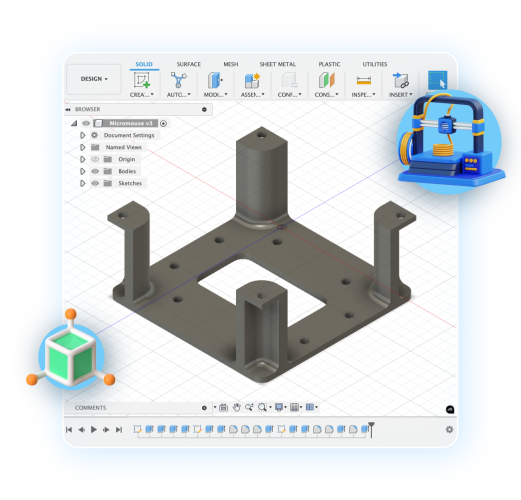
3D CAD: Several prototypes were carefully sketched and reiterated thanks to history tracking in software like Fusion 360.

3D Slicing: Infill percentage and support type were thoughtfully chosen, considering the structural loads on the chassis and multiple cavities.

3D Printing: PETG polyester material was prioritised due to its durability and good layer adhesion compared to other materials like ABS & PLA.

Image Analysis & Path Planning

The different processing techniques utilised to make the robot understand its surroundings.


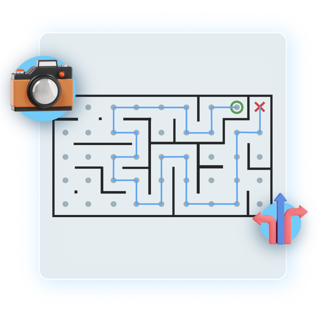
OpenCV: Various image manipulation techniques were implemented including erosion, dilation, opening and closing in order to separate the maze from the background.

Path Planning Methods: Depending on the shape and complexity of the maze, a suitable method is used including Dijkstra, RRT, BFS and DFS.

Output Commands: A chain of commands is generated from the path generated, all to an (image-to-world) scale with relevant vector angles computed.

Control System

How the robot makes use of its input sensor data and path plans to execute commands to output modules like the motors.


Sensor Data Filtering: Techniques like a moving average filter were applied to reduce noise and provide more stable input data for accurate decision-making.

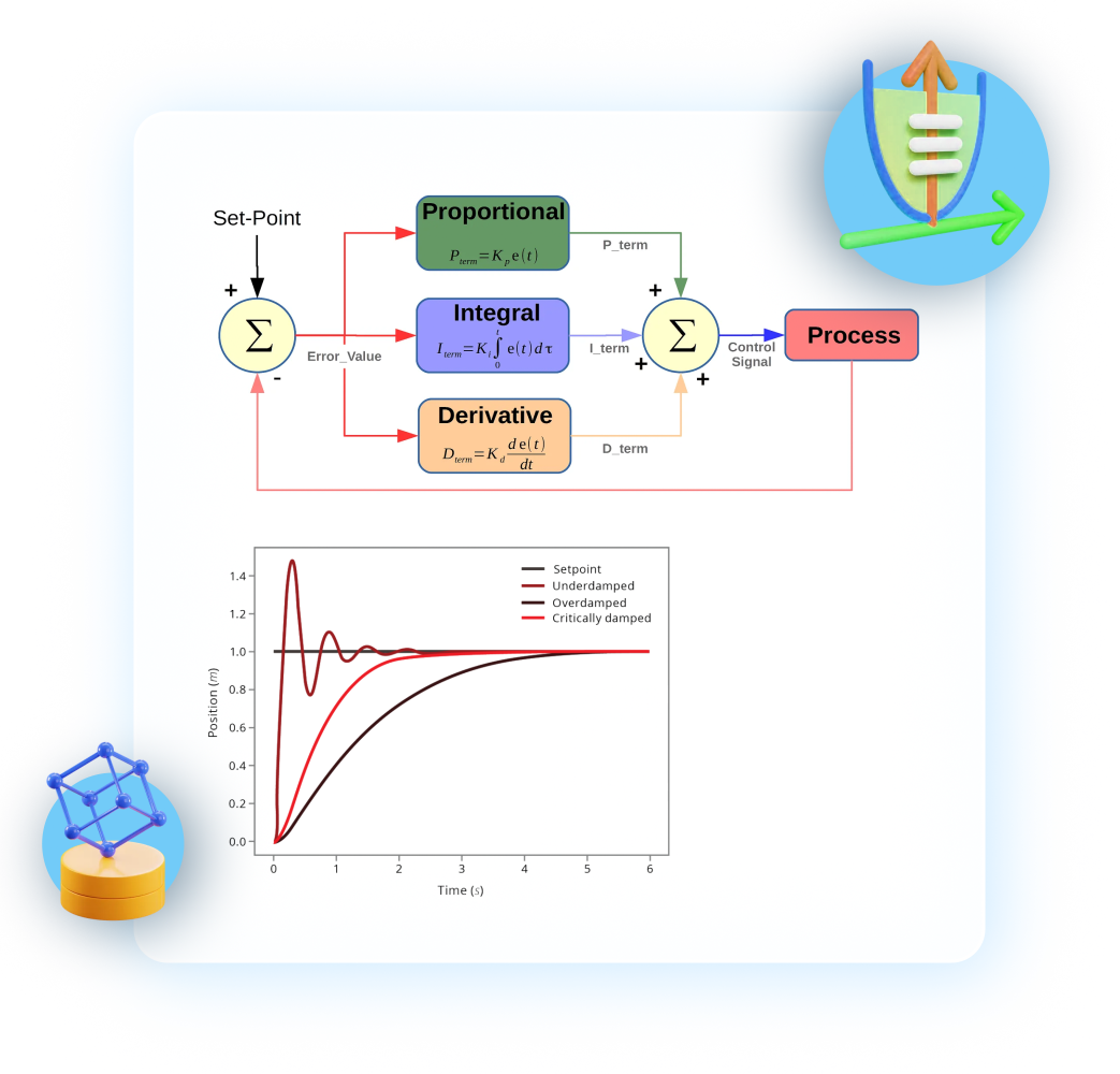
PID Control: This manages the robot's straight driving and accurate turning, utilising input from IMU and time-of-flight sensors to adjust motor outputs, and requires extensive tuning.

Position Tracking: The robot's position was tracked using the IMU module and motor encoders, with double integration of acceleration data to calculate its X and Y coordinates.

Contact Me